DCD-SEMI Introduces eSPI Combo for Next-Generation Intel-Based Platforms
DESPI eSPI Controller IP Core and DESPI eSPI IP Core Target deliver a complete, high-speed eSPI interface solution for FPGA and ASIC designs.
The DDMA is a four-channel Direct Memory Access Controller.
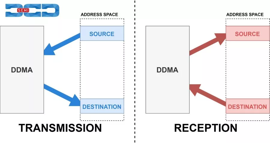
The DDMA is a four-channel Direct Memory Access Controller. Its purpose is to transfer data between memories and peripherals to reduce CPU utilization during data transfers. It can be programmed by the CPU via a 32-bit or 8-bit native interface. The DDMA can perform data transactions of configurable size over 32-bit address space. A single transaction size can be set in a range from 1B to 16MB. To limit the negative impact of different reads and writes timing the DDMA features transfer data buffer. This buffer is a 32-bit FIFO memory with configurable depth.
Data transactions can be triggered either by hardware or software. Hardware initialization is achieved via the Peripheral Request Interface, while software initialization is done by the CPU via registers. The Peripheral Request Interface is used by external controllers (peripherals) to set data transaction requests on specific DDMA channel. Each of the DDMA channels has a set of Peripheral Request Interface signals associated with it. Peripherals can request the transmission or reception of data. When multiple channels await data transfer the arbitration process utilizes a round-robin algorithm.
There are four DDMA channels. Each has its configuration registers and enable bit.
The DDMA offers three transfer modes:
* SINGLE – single data transfer on request,
* NORMAL – one data block transfer on request,
* BLOCK – all data blocks transfer on request.
They are distinguished by the amount of data transferred on a single request. Data transaction is divided into blocks. It is possible to configure the number of block bytes and blocks in a transaction. Data transfer is performed between the data source and the data destination. The DDMA channel can perform reads and writes on 32-bit, 16-bit, and 8-bit data which is separately configurable for both source and destination. Source and destination addresses can be freely configured.
The DDMA offers three addressing modes:
* INC – increment address after each data access,
* DEC – decrement address after each data access,
* FIXED – the address is fixed.
Apart from the above, the IP Core has three sources and destination address reload options:
* TRANSACTION – address is reloaded after the full transaction,
* BLOCK – the address is reloaded with each block transferred,
* NEVER – the address is never reloaded.
Address, block, and byte registers are double-buffered so that if they are changed while the channel is busy, the change does not take effect until the current data transfer is over.
Each channel has status and transfers status flags. Channel status is defined as BUSY, PENDING, or IDLE. Transfer status flags inform about the amount of data that has been sent by the channel. Proper flags are set after transmitting a single data, block, or transaction. Each transfer status flag is masked which allows for generating an interrupt request when a specific data transfer situation occurs.
Note: some files may require an NDA depending on provider policy.

Direct Memory Access Controller is a DMA IP core from Digital Core Design listed on Semi IP Hub.
Engineers should review the overview, key features, supported foundries and nodes, maturity, deliverables, and provider information before shortlisting this DMA IP.
Yes. Buyers can compare this product with similar semiconductor IP cores or IP families based on category, provider, process options, and structured technical specifications.