
Vendor: InCirT GmbH Category: PLL

6GHz-12.5GHz PLL in GF 22nm FDX

Ultra-low jitter, low-power ring-oscillator-based PLL- 6GHz-12.5GHz in GF 22nm FDX

GlobalFoundries 22nm FDX Silicon Proven View all specifications

Overview

This PLL is implemented in Global Foundries 22FDX CMOS technology It offers ultra-low jitter (600fs-rms at 12.5GHz) and low power consumption (5.3mW at 12.5GHz), with an operational range from 6GHz to 12.5GHz. Its ultra-compact footprint makes it an excellent choice for SoC designs that require multiple clock domains. As an integer-N PLL, it provides designers with the flexibility to optimize clock domains across the entire system. 

Key features

  • Output frequency: 6GHz-12.5GHz 
  • Small area: 95x85 um2 
  • Low jitter: 600fs rms-jitter at 12.5GHz 
  • Low power: 5.3mW at 12.5GHz 
  • Reference clock: 50MHz 
  • Programmable integer divider 
  • GF 22FDX CMOS technology 
  • Silicon Proven 

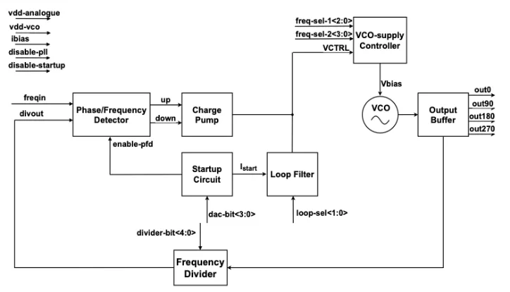
Block Diagram

Applications

  • SoCs requiring multiple-clock domains 
  • ADC and DAC 
  • High-speed SerDes 

What’s Included?

  • GDSII layout 
  • Verilog (or SystemVerilog) model 
  • Integration support 
  • DRC, LVS reports 
  • Datasheet including characterization results 
  • CDL netlist for LVS 
  • LEF files 
  • Verification report 

Silicon Options

Foundry Node Process Maturity
GlobalFoundries 22nm FDX Silicon Proven

Specifications

Identity

Part Number
AIX-PLL-12P5G-GF22DFX
Vendor
InCirT GmbH
Type
Silicon IP

Provider

HQ: Germany

Learn more about PLL IP core

Creating a Frequency Plan for a System using a PLL

How do you ensure that every part of a system receives the clock it needs—without wasting power or sacrificing performance? The answer lies in creating a well-structured frequency plan built around a PLL.

Specifying a PLL Part 3: Jitter Budgeting for Synthesis

This white paper is aimed at system architects and physical implementation leaders working on the design of SoCs. It can be confusing to understand the impact of different jitter sources and how to calculate a jitter budget when specifying a digital system. This white paper explains how jitter changes the period of a clock and how to ensure that jitter has correctly been accounted for in the calculations for timing closure.

Specifying a PLL Part 2: Jitter Basics

This article explains a some of the key terminology and parameters commonly used to describe jitter. It will also help clarify the most important parameters for a some PLL applications, allowing the designer to better understand what is required from a PLL.

Specifying a PLL Part 1: Calculating PLL Clock Spur Requirements from ADC or DAC SFDR

In high end RF systems, such as 5G radios, the requirements are so stringent that the source of this strongest unwanted tone can be the PLL. This article outlines how spurs in the input clock to the ADC or DAC may limit the SFDR. This in turn will set the requirements for the spurs for the input clock (from a PLL), in order to achieve a specific SFDR.

Achieving Groundbreaking Performance with a Digital PLL

This article compares analog, first-generation digital, and second-generation digital PLLs. It evaluates which type of PLL may be best in which situation. It further discloses a roadmap into other application areas, including general purpose / logic clocking, and regular low-jitter PLLs.

Frequently asked questions about PLL IP cores

What is 6GHz-12.5GHz PLL in GF 22nm FDX?

6GHz-12.5GHz PLL in GF 22nm FDX is a PLL IP core from InCirT GmbH listed on Semi IP Hub. It is listed with support for globalfoundries Silicon Proven.

How should engineers evaluate this PLL?

Engineers should review the overview, key features, supported foundries and nodes, maturity, deliverables, and provider information before shortlisting this PLL IP.

Can this semiconductor IP be compared with similar products?

Yes. Buyers can compare this product with similar semiconductor IP cores or IP families based on category, provider, process options, and structured technical specifications.

×
Semiconductor IP