Vendor: Cadence Design Systems, Inc. Category: HBM

Simulation VIP for HBM

In production since 2015 on dozens of production designs.This Cadence® Verification IP (VIP) provides support for the JEDEC® High…

Overview

In production since 2015 on dozens of production designs.

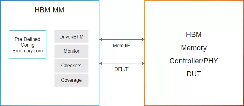
This Cadence® Verification IP (VIP) provides support for the JEDEC® High-Bandwidth Memory (HBM) DRAM device standard. It provides a mature, highly capable compliance verification solution that supports simulation, formal analysis, and hardware acceleration platforms, making it applicable to intellectual property (IP), system-on-chip (SoC), and system-level verification. The Memory Model for HBM models a single channel of HBM DRAM; this model can be replicated for multiple channels and multiple ranks. The Memory Model for HBM runs on all leading simulators, and leverages the industry-standard Cadence Memory Model core architecture, interface, and use model.

The HBM DRAM standard is an industry-leading, low-power, double-data-rate, high-data-width, volatile (DRAM) device memory standard for storage of system code, software applications, and user data. The HBM DRAM Memory Device Standard is designed to satisfy the performance and memory density demands of the leading-edge mobile devices. The Memory Model for HBM supports single-channel implementation version of the following HBM DRAM specifications, and can be used eight times to model a single 8-channel device.

Supported specification: The VIP for HBM Memory Model supports JEDEC specifications: JESD235B Rev 2.60 (HBM2E), JESD235B Rev 2.50 (HBM2) and JESD235 Rev 1.27 (HBM), JESD235C Rev 3.30

Key features

  • Speed (MHz)
    • 1800MHz (3.6 Gbps/pin)
  • Device Density
    • Supports a wide range of device densities from 1Gb to 24Gb
  • Size and Modes
    • Programmable size: Single channel can be replicated eight times to generate a 8-channel mode
    • Support for 1Gb, 2Gb, and 4Gb per channel in Legacy Mode; Up to 24Gb in Pseudo Channel Mode
  • Pseudo Channel Mode
    • Divides a channel into two individual sub-channels of 64 bit I/O each
  • 8H and 12H stack
    • Pseudo Channel Mode 8H configuration - 8Gb, 12Gb, and 16Gb
    • Pseudo Channel Mode 12H configuration - 12Gb, 18Gb, and 24Gb
  • Row and Column Width
    • Higher density HBM2E configuration supported by additional CA8 and RA6 Row and Column pins
  • I/O Signals and Buses
    • All I/O signals including RD, RR, and RC are supported by HBM
  • Clocking and Reset
    • Differential clock inputs (CK_t/CK_c) and Active Low Reset Line (reset_n)
  • Command Decode
    • Mode Register Set
    • Precharge Same Bank, All Bank
    • Refresh Single Bank, Refresh All Bank
    • Reset, Activate
    • Read/Write, Read/Write with Auto Precharge
    • Power Down Entry, Self Refresh Entry, Power Down/Self Refresh Exit
  • Initialization
    • Initialization sequence with all the timing checks (also IEEE 1500 Stable Power Initialization). Initialization can be skipped
  • SID
    • The stack ID (SID) acts as a bank address bit in command execution
  • Error-Correcting Code
    • Support ECC with one bit per data byte; the HBM Model does not compute any ECC. ECC bits are not included in parity calculation when Write or Read DQ Parity Function is enabled
  • Data Mask and Data Bus Inversion
    • Data on the bus can be inverted during both read and write to save power; both Data Mask and Data Bus inversion features can be set through mode registers
  • C/A and Data Parity Check
    • Checks the C/A parity for each command before execution, write parity for each write data word (DQ, DM,DBI), read parity generation for each read data word
  • Targeted Row Refresh Mode
    • Refresh the rows adjacent to the TRn that encountered MAC limit; there could be one or two target rows in a bank associated to one victim row
  • IEEE 1500/DFT
    • HBM DFT support using IEEE 1500 interface feature:
      • LFSR, AWORD and DWORD MISR
      • LFSR compare (Sticky bit)
      • Hard Lane repair and Soft lane repair
      • Extest TX and Extest RX
      • Device ID and Temperature Instructions
      • Mode Register Dump Set
      • User configurable MBIST register
      • Loopback Test Mode
      • Supports DFT and training between the host and HBM device
    • Loopback Test Mode
      • HBM DFT support using loop back mode feature
    • Soft Lane Repair and Hard Lane Repair
      • Interconnect lane remapping to help recover functionality of the HBM stack
      • Lane remapping independent for each channel
      • Retain the remapped lane information even when power is removed from stack
      • Except CK_t, Ck_c , CKE and AERR, all other I/Os can be remapped using AWORD and DWORD Remapping
    • DWORD Repair Mode
      • Two Repair Mode for DWORD remapping:
        • In Mode 1, it is allowed to remap one lane per byte; no redundant pin is allocated in this mode, and DBI functionality is lost for that byte only, however other bytes continue to support DBI function as long as the Mode Register setting for DBI function is enabled
        • In Mode 2, it is allowed to remap one lane per double byte; one redundant pin (RD) per double byte is allocated in this mode, and DBI functionality is preserved
      • RD, RC, and RR
        • Support Redundant Row, Column values for AWORD Repair, and Redundant Data(4 bits) value supported for DWORD Repair functionality
      • Data Width
        • 128-bit wide data bus
        • Pseudo channel mode with 64-bit data per pseudo channel
        • DDR for Command and Data Phase
      • Differential ck, rdqs, and wdqs
        • Differential clock and data referenced to strobes RDQS_t/RDQS_c and WDQS_t/WDQS_c
        • 1 strobe pair per DWORD
        • Read and Write strobes for each pseudo channel are driven and read simultaneously
      • Bank Groups
        • Modeling the concept and the timing associated with back-to-back accesses to the same and different bank group
      • Refresh
        • All bank, per-bank and self-refresh; refresh timing check; Normal mode refresh, Self refresh, Temperature controller self refresh supported
      • Cattrip and Temp Pin
        • HBM cattrip and Temp Pins functionality support for Temperature-controlled Refresh and Catastrophic Temperature Sensor

Block Diagram

Files

Note: some files may require an NDA depending on provider policy.

Specifications

Identity

Part Number
Simulation VIP for HBM
Vendor
Cadence Design Systems, Inc.

Provider

Cadence Design Systems, Inc.
HQ: USA
If you want to achieve silicon success, let Cadence help you choose the right IP solution and capture its full value in your SoC design. Cadence® IP solutions offer the combined advantages of a high-quality portfolio, an open platform, a modern IP factory approach to quality, and a strong ecosystem. Now you can tackle IP-to-SoC development in a system context, focus your internal effort on differentiation, and leverage multi-function cores to do more, faster. The Cadence IP Portfolio includes silicon-proven Tensilica® IP cores, analog PHY interfaces, standards-based IP cores, verification IP cores, and other solutions as well as customization services for current and emerging industry standards. The Cadence IP Factory provides you with an automated approach to the customization, delivery, and verification of SoC IP. As a result, you can spend more time on differentiation, with the assurance that you'll meet your performance, power, and area requirements. Choosing Cadence IP enables you to design with confidence because you have more freedom to innovate your SoCs with less risk and faster time to market.

Learn more about HBM IP core

Making Strong Error-Correcting Codes Work Effectively for HBM in AI Inference

LLM inference is increasingly memory-bound, and HBM cost per GB now dominates system cost. Today’s HBM stacks include short on-die ECC, which tightens binning, raises price, and locks reliability policy inside the device. This paper asks a simple question: can we tolerate a much higher raw HBM bit error rate (BER) and still keep end-to-end correctness and throughput, without changing the HBM PHY or the fixed 32B transaction size?

High Bandwidth Memory Evolution from First Generation HBM to the Latest HBM4

HBM4 is the latest generation of the High Bandwidth Memory (HBM) that has become analogous to the Artificial Intelligence (AI) boom that is everywhere in today’s world. HBM is also increasingly being used in other applications like Data centers, autonomous driving systems, servers, cloud computing just to mention few domains where bandwidth and performance in a key requirement.

Breaking the HBM Bit Cost Barrier: Domain-Specific ECC for AI Inference Infrastructure

High-Bandwidth Memory (HBM) delivers exceptional bandwidth and energy efficiency for AI workloads, but its high cost per bit, driven in part by stringent on-die reliability requirements, poses a growing barrier to scalable deployment. This work explores a systemlevel approach to cost reduction by eliminating on-die ECC and shifting all fault management to the memory controller.

High Bandwidth Memory (HBM) Model & Verification IP Implementation - Beginner's guide

With ever increasing need for very high operating frequency of graphics (GPU) or general purpose (CPU) processors, the limited memory bandwidth forms a bottleneck to extract maximum performance out of a system. To add to this, low power consumption, form factor of the memory devices also play significant roles in optimal and efficient solutions.

Frequently asked questions about LPDDR IP

What is Simulation VIP for HBM?

Simulation VIP for HBM is a HBM IP core from Cadence Design Systems, Inc. listed on Semi IP Hub.

How should engineers evaluate this HBM?

Engineers should review the overview, key features, supported foundries and nodes, maturity, deliverables, and provider information before shortlisting this HBM IP.

Can this semiconductor IP be compared with similar products?

Yes. Buyers can compare this product with similar semiconductor IP cores or IP families based on category, provider, process options, and structured technical specifications.

×
Semiconductor IP