What is CCSDS SCCC Demapper and Turbo Decoder?
CCSDS SCCC Demapper and Turbo Decoder is a Channel Coding IP core from Small World Communications listed on Semi IP Hub.
4 state CCSDS compatible serially concatenated convolutional code (SCCC) demapper and turbo decoder
The SCD02C is a fully compatible CCSDS SCCC [1] error control decoder. Nineteen different interleaver sizes from 8640 to 65520 bits are implemented. Twenty seven different code rates R from 0.355 to 0.899 can be selected, giving bandwidth efficiencies from 0.711 to 5.392 bit/sym, excluding header and pilot symbols.
For the code, both the outer and inner encoders use a four state rate 1/2 systematic recursive convolutional code. The outer rate 1/2 code is punctured to a rate of 2/3. The outer four bit tail is punctured to three bits. The inner rate 1/2 code uses different forms of puncturing for the systematic and parity bits, with the four bit tail not punctured. The interleaver size is of size I = 1.5K+3, where K is the number of information bits, which ranges from 5758 to 43678.
The number of coded bits is 8100s, where s is the number of bits per symbol, ranging from s = 2 for QPSK to 6 for 64APSK. To allow continuous decoding, a ping–pong symbol deinterleaver is used to buffer the input data to be decoded. For the turbo decoder, a ping–pong output memory is used to output the decoded data.
Np = 60 MAP02C four state rate 1/2 MAP decoder cores are used with the SCD02CF core, to iteratively decode the SCCC turbo code. The suffix F for the core name indicates the use of 60 MAP decoders. Suffixes 1, 2, 3, 4, 5, 6, 7, 8, 9, A, B, C, D, E and G correspond to Np = 1, 2, 3, 4, 5, 6, 8, 10, 12, 15, 20, 24, 30, 40 or 120, respectively.
The Log–MAP algorithm for maximum performance or the max–log–MAP algorithm for minimum complexity and highest speed can be selected. The extrinsic information can be optionally scaled and limited with each half iteration, improving performance with max–log–MAP decoding.
The reverse sliding window algorithm is used with sliding window lengths of L = 32 or 64 for Kd/Np > L and L = Kd/Np otherwise, where Kd = I for inner decoding and Kd = K+2 = 2I/3 for outer decoding. Eight–bit quantisation is used for near optimum performance.
The turbo decoder can achieve up to 787 Mbit/s with 10 iterations and max–log–MAP decoding using a 356 MHz internal clock (ACM = 27, Np = 60). Log–MAP decoding decreases speed by about 24%. Optional early stopping allows the decoder to greatly reduce power consumption with little degradation in performance.
The VHDL cores can be used with Xilinx Integrated Software Environment (ISE) or Vivado software to implement the core in Xilinx FPGA’s. VHDL cores are available on request for ASIC, Intel/Altera, Lattice and Microsemi/ Actel designs.
Table 1 shows the resources used for Kintex UltraScale+ devices. Resources for Virtex–5, Virtex–6, Spartan–6, 7–Series and UltraScale devices are similar to those for UltraScale+. The MODE input can be used to select various decoder implementations. Three clocks are used for the input symbols, turbo decoder and decoded data. No other resources are used.
Table 1: Resources used.
| MAPs (Np) | LUTs Max–log–MAP | LUTs Log–MAP | 18KB BRAMs |
|---|---|---|---|
| 60 | 89,297 | 116,074 | 180 |
Table 2 shows the PCD02CF performance achieved with various Xilinx parts and K = 43678 (ACM = 27). Tcp is the minimum clock period over recommended operating conditions. These performance figures may change due to device utilisation and configuration. Note that Zynq devices up to XC7Z020 and from XC7Z030 use programmable logic equivalent to Artix–7 and Kintex–7 devices, respectively.
Table 2: Performance of Xilinx parts.
| Xilinx Part | Tcp (ns) | f (MHz) | fd (Mbit/s) |
|---|---|---|---|
| XC7A200T–1 | 9.042 | 110.6 | 244.7 |
| XC7A200T–2 | 7.484 | 133.6 | 295.6 |
| XC7A200T–3 | 6.609 | 151.3 | 334.8 |
| XC7K160T–1 | 6.513 | 153.5 | 339.7 |
| XC7K160T–2 | 5.466 | 182.9 | 404.8 |
| XC7K160T–3 | 4.978 | 200.9 | 444.4 |
| XCKU035–1 | 5.331 | 187.6 | 415.0 |
| XCKU035–2 | 4.518 | 221.3 | 489.7 |
| XCKU035–3 | 3.828 | 261.2 | 578.0 |
| XCKU3P–1 | 3.536 | 282.8 | 625.7 |
| XCKU3P–2 | 3.059 | 326.9 | 723.2 |
| XCKU3P–3 | 2.809 | 356.0 | 787.6 |
MODE = 0, Id = 10, ACM = 27, L = 32, Np = 60
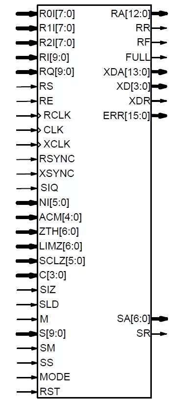
Signal Descriptions
| Signal | Description |
|---|---|
| ACM | Advanced Coding and Modulation select (1 to 27) |
| C | MAP Decoder Constant (0–11) |
| CLK | System Clock |
| ERR | Estimated LLR Channel Error (0 to 8100m) |
| FULL | Decoder Full (new data not accepted) |
| LIMZ | Extrinsic Information Limit (1–127) |
| M | Early Stopping Mode: 0 = no early stopping; 1 = early stopping |
| MODE | Implementation Mode: 0 = Max–log–MAP 1 = Log–MAP |
| NI | Number of Iterations Minus One (0–63). NI = Id–1, where Id is number of iterations |
| R0I | First Received LLR Data |
| R1I | Second Received LLR Data |
| R2I | Third Received LLR Data |
| RA | Received Data Address |
| RCLK | Received Data Clock |
| RE | Received Data Enable |
| RF | Received Data Finish |
| RI | Received Descrambled Inphase Data |
| RQ | Received Descrambled Quadrature Data |
| RR | Received Data Ready |
| RS | Received Data Start |
| RSYNC | RCLK and CLK equal |
| RST | Synchronous Reset |
| S | Symbol Value (10–bit) |
| SA | Symbol Address |
| SCLZ | Extrinsic Information Scale (1–32) |
| SIQ | Inphase and Quadrature Select: 0 = No Demapping (LLR data input to R0I to R2I); 1 = Demapping (data input to RI and RQ) |
| SIZ | Internal SCLZ and LIMZ Select: 0 = External SCLZ, LIMZ; 1 = Internal SCLZ, LIMZ if MODE = 0 |
| SLD | Sliding window select: 0 = small window (Lmax = 32); 1 = large window (Lmax = 64) |
| SM | Symbol Memory Select: 0 = ROM; 1 = RAM |
| SR | Symbol Ready |
| SS | Symbol Start |
| XCLK | Decoded Data Clock |
| XD | Decoded Data (4 bits, last symbol 2 bits) |
| XDA | Decoded Data Address |
| XDR | Decoded Data Ready |
| XSYNC | XCLK and CLK equal |
| ZTH | Early Stopping Threshold (1–127) |
The MODE input is used to select various decoder implementations. Note that MODE is a “soft” input and should not be connected to input pins or logic. This input is designed to minimise decoder complexity for the configuration selected.
Note: some files may require an NDA depending on provider policy.
CCSDS SCCC Demapper and Turbo Decoder is a Channel Coding IP core from Small World Communications listed on Semi IP Hub.
Engineers should review the overview, key features, supported foundries and nodes, maturity, deliverables, and provider information before shortlisting this Channel Coding IP.
Yes. Buyers can compare this product with similar semiconductor IP cores or IP families based on category, provider, process options, and structured technical specifications.